Maytech.cn--Maytech official website
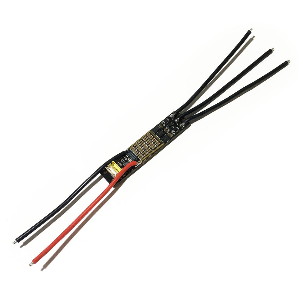
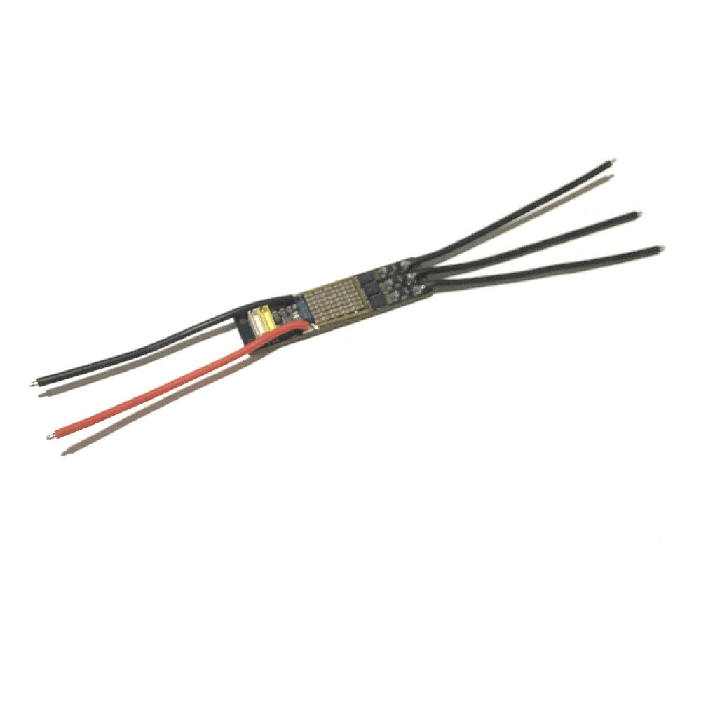
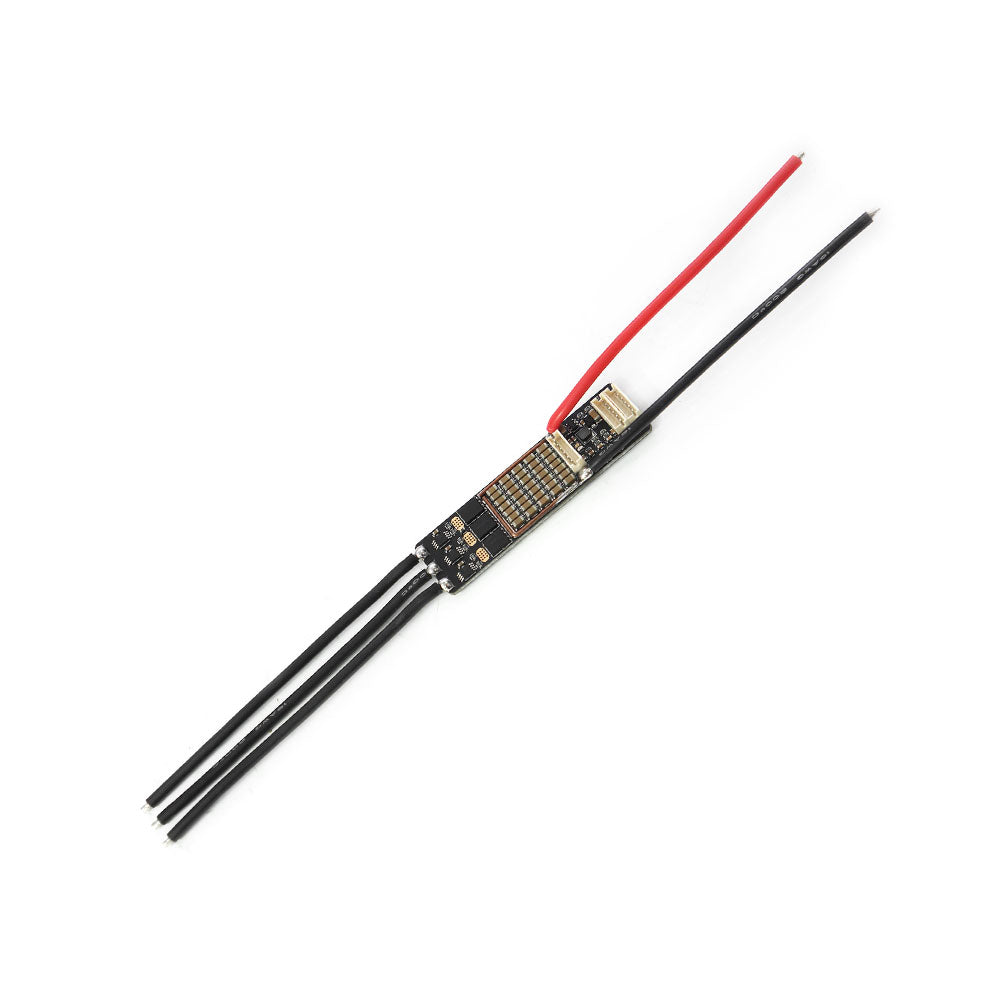
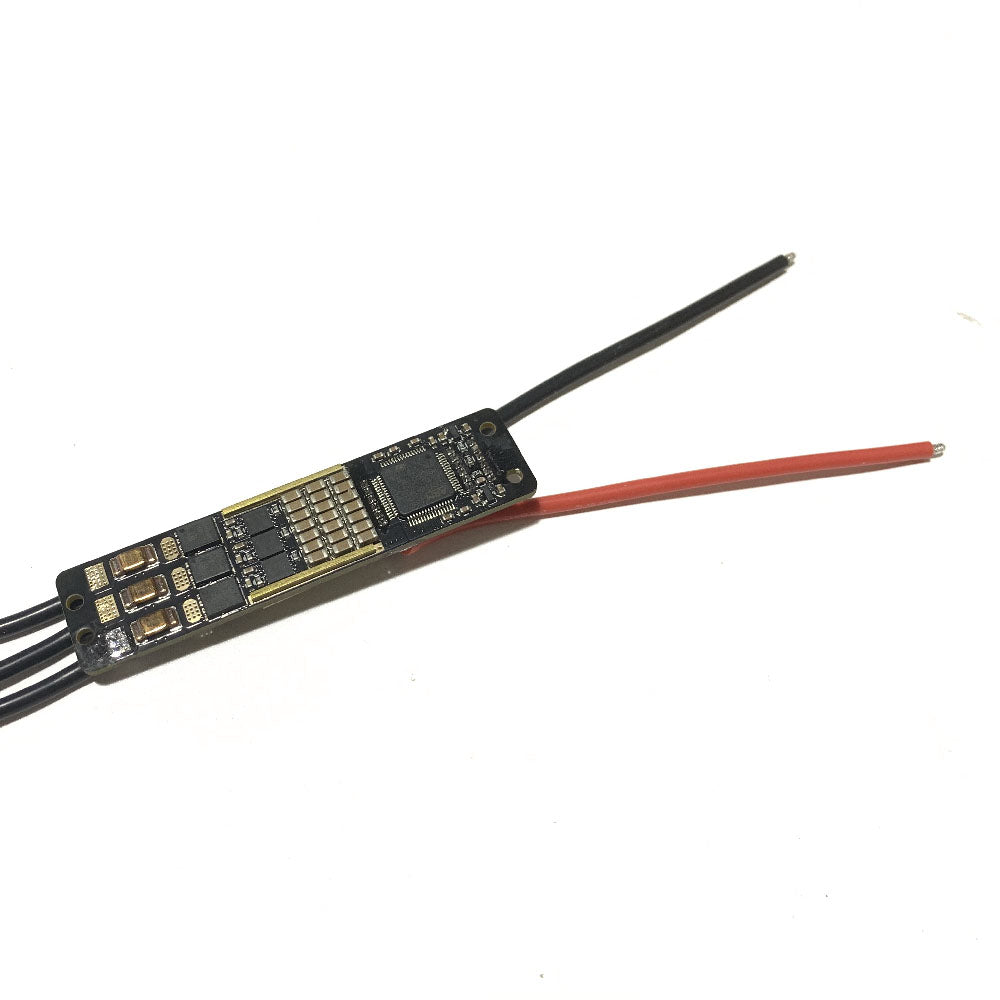
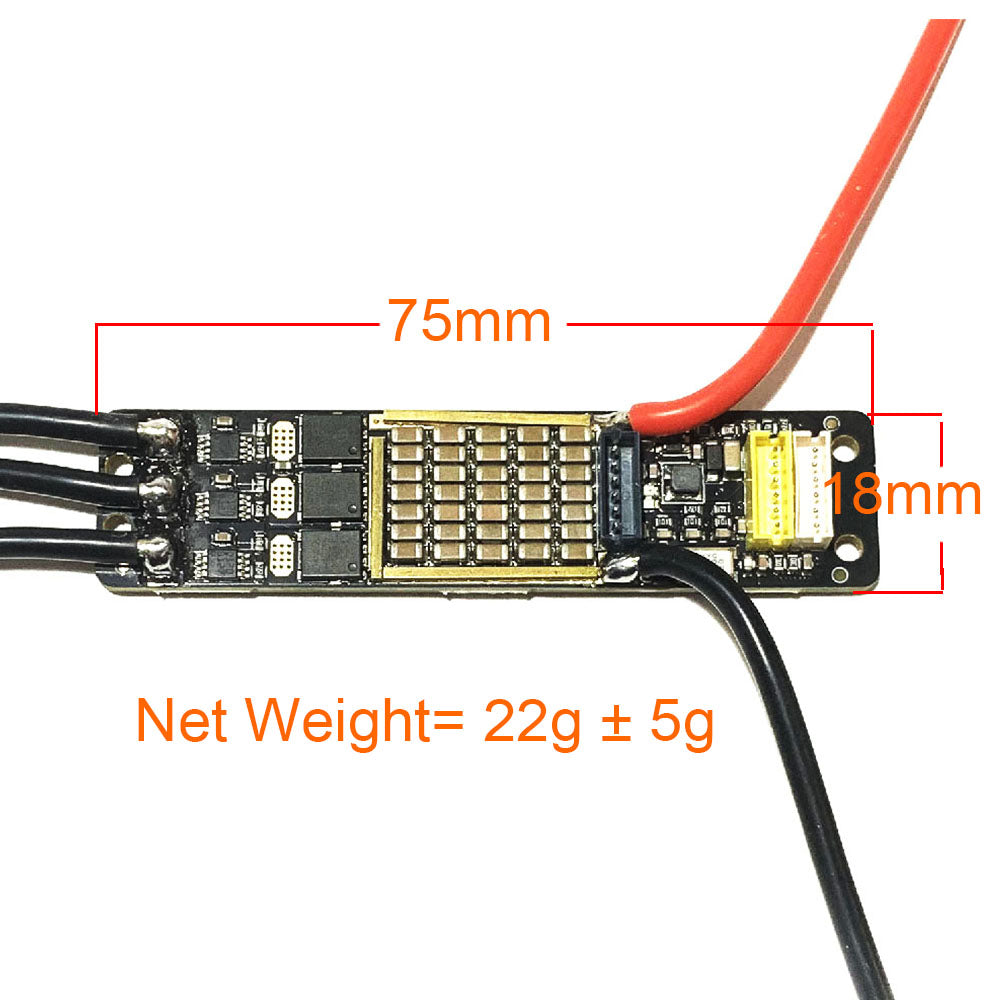
MTSPF6.0M Mini 10S 42V V6 based 30A Speed Controller SUPERFOC ESC
MTSPF6.0M Mini 10S 42V V6 based 30A Speed Controller SUPERFOC ESC
Couldn't load pickup availability
If you want to use other cheaper but slower shipping method, please contact agnes@maytech.cn
Shipping time by DHL or UPS is fast, normally 3-7 days arrive to you.
Maytech MTSPF6.0M Mini SuperESC 35g 10S 42V V6 based Controller 30A for Combat Robots/Delivery Robots Arm Robotics/Camera Motorized Dolly / Smart Robot Lawnmower
Firmware: Default and recommend firmware is 5.2.
| Model No. | MTSPF6.0M | Cont. Current | 30A |
| Burst Current | 50A | Input Voltage | 42V(10S) |
| Hardware | Based on V6.0 | Firmware | Updatable |
| Software | VESCTOOL Compatible | FOC | Yes, can work |
| Size |
65mm*20mm | Compatible Motor | Sensored / Sensorless Motor |
| Net Weight | 35g/pcs | Application |
Notice:
Only connect CAN L and CAN H ! GND pins and 5V should never be connected in a V6/V75 based SUPERFOC ESCs or VESC array.
Function overview
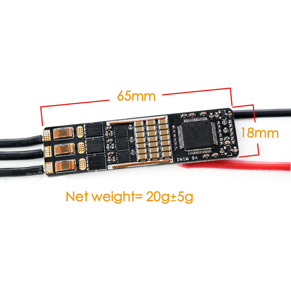
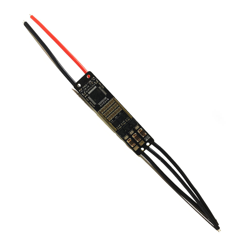
- The smallest VESCTOOL Compatible V6 based controller on the market, with a size of only 18x65mm, can be used for miniaturized equipment, such as smart cars, micro robots, electric roller skates, drones, electric models, etc.
- Based on powerful VESCTOOL software and hardware, it supports PWM analog voltage UART and USB speed signal input. It supports sensored and sensorless brushless motors and brushed motors, and supports square wave and FOC modes.
- Support up to 10S lithium battery,over‐current/over‐temperature/over‐voltage protection.
- Support VESCTOOL, UART is enabled by default in the factory firmware. It is recommended to connect controller through the serial port of the host computer. If you need a USB connection, you can use the random adapter cable to connect.
- Recommended matching scheme: 6S lithium battery plus MTO2830 with Hall sensoredbrushless motor.
Port Definition:
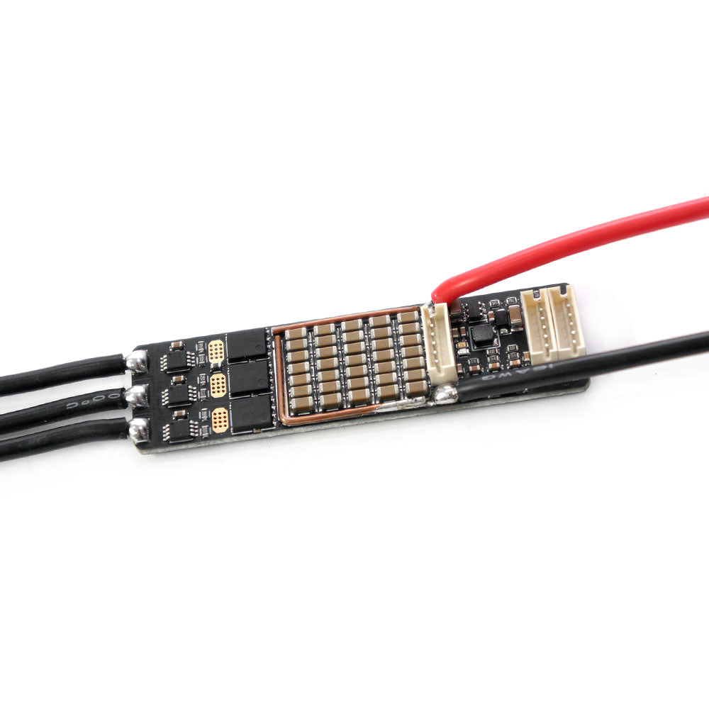
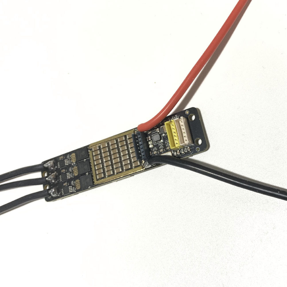
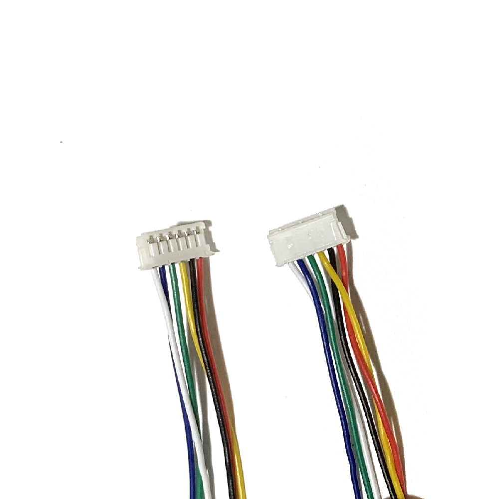
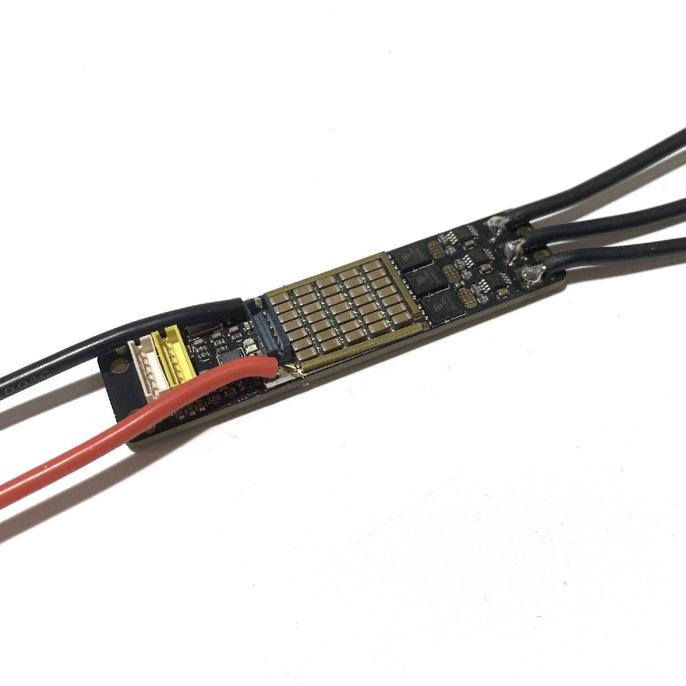
- GND1/2, DP(Data postive), DM(Data Minus/Negative): USB port for programming.
- GND1/2, PPM, +5V: PPM port to connect PPM transceivers.
- SWC(CLK), SWD(DIO), GND1/2, 5V: SWD port, to get direct access to the Chipset. Diagnostics, debugging, and real time data.
- A1(ADC1), A2(ADC2), TX, RX, GND1/2, 5V: COMM port for various kinds of other communication methods like I2C, ADC, Uart. You can use your Arduino or Raspberry Pi to control the VESC.
- 5V, TEMP, HAll1, Hall2, Hall3 GND: Sensor port for motor Hall sensors (ABI, HALL, magnetic precision encoders).
-DP on the pin refers to Data Positive. DM refers to Data Minus. It is necessary to connect to the computer by making a USB adapter. The standard USB port has four wires: two power supplies positive and negative, and two data positive and negative. Players only need to connect the power negative (GND) and data positive and negative three wires to the computer USB port, no need to connect the power positive supply.
PS: (GND1 and GND2 are same, for above ports containing GND1/2, you can just select one to use).


Hardware Overview:
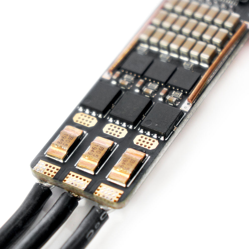
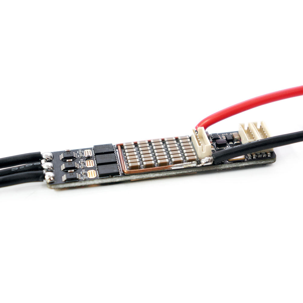
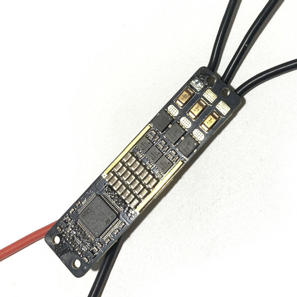
- 4-layers 3OZ PCB, main power loop adds copper bars to reduce resistance.
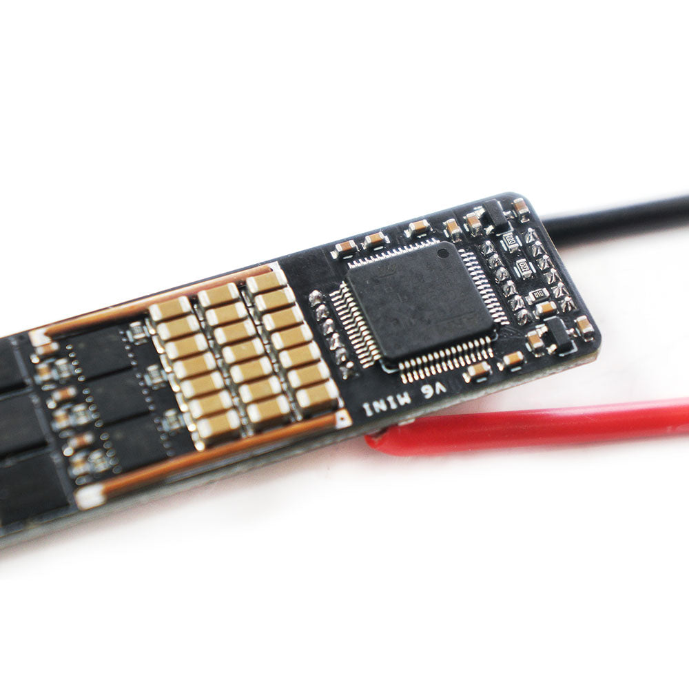
- Use Swiss STM32F405RT6 to ensure strong computing power
- 3-channel independent driver chip LM5113SDE (WSON package 4mm*4mm) from American TI (Texas Instruments) company, can withstand 100V.
- 6pcs ON’s 60V/2.4 milliohm NTMFS5C628NLT1G MOSFET, DFN 5.5mm*6mm, theoretically each MOS can withstand 150A peak current.
- 3pcs Current Sense Resistor from CSS2H-2512R-L500, 0.5 milliohm copper-manganese alloy resistors, can withstand max 100A peak current.
- 3pcs Current Sense Amplifier from AD (Analog Devices) company, Model AD8417BRMZ, small size high accuracy, with low temperature drift coefficient.
- Main DC-DC chip is LMR16006 from American TI company, convert high voltage (Under 60V) to 5V, max output 0.6A.
- Slave DC-DC chip is MCP1700T-3302E/TT from Microchip company, convert 5V to 3.3V power for components.
- 56pcs 2u2 100V high voltage chip capacitor, with 123.2μf gross capacity.
Attention Points when you receive the controller Please:
All products had been double checked and tested one by one before shipment, only if the products are working normally would be shipped out.
- When you receive the controller, please test without load and do not connect motor, first check if the controller can successfully connect to your computer, if ok, then connect to motor and you can start to adjust parameters.
- Do not use switching power supply, the instant voltage when switching power supply connect to controller is very high, which would easy damage the controller.
- Do not push the throttle too hard when test without load, gently and slowly speed up.
- Be cautious when adjust parameters, if parameters set mistake, would also easy damage the controller.
- Please must remember to change to corresponding modes when you adjust parameters, for example, the controller default mode is BLDC mode, but if you want to detect FOC mode and adjusted FOC parameters, at this time if mode in VESCTOOL didn't change to FOC mode, then when you push throttle, would easy burn the controller, same as FOC mode.
-
In FOC mode, ERPM suggest to control in 30000-40000; In BLDC moed, ERPM suggest to control in 50000-60000, otherwise driver IC would easy to be damaged. ERPM= motor pole pairs number * KV * Voltage
ERPM= motor pole pairs number * KV * Voltage - If you use UART port, the wire better do not over 0.5m or even shorter, and better use Stranded wire.
- For V4 based controller:
Do not suggest to use FOC mode, suggest to use BLDC mode.
If need to use FOC mode, then must use voltage under 20V.
- The above are only suggestions based on the experience of our engineers. how to actually operate is up to you. Parameters for different setup is also different, please noted
Related Products: (Click the following pictures to check more products)
Maytech MTSKR2005WF New Waterproof Remote for Esk8 Only with 3 Speed Modes
Maytech Brushless Outrunner Sensored Motors
Maytech VESCTOOL Compitable Controller:
Share
